
Introduction lab; the transitional lab from Computer Hardware to Computer Architecture. Introduces the use of GSM AT commands and a refresher on communication with Espressif Systems and Arduino style 32-bit MCU.
Material(s) Required
- IlI9488 Display or Similar see here (Scroll to Display list)
- ESP32-S3 Devkit or Similar see here
- A7670G with Breakout (or any SIMCOM NA/Global GSM Modem)
- Activated SIM Card
- Assorted Dupont Wire
- Breadboard (optional)
- Computer (Windows, MacOS, or Linux)
Part 1 – Setup
- Download and Install Arduino IDE from here
- Open Arduino IDE
- Go to the Boards Manager
- On the top toolbar: Go to Tools > Board > Boards Manager
- Or use the keycombo Ctrl + Shift + B

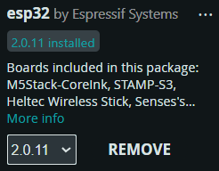
4. Search ‘Esp32’
5. Install version 2.0.11 of ‘esp32’ by Espressif Systems
6. Plug your ESP32 into your computer
7. Once plugged in select your board from the Upper Toolbar if it is not selected for you already

Part 2 – Modem Setup
| Modem | Description | ESP32 Pin |
| 5-12V | Power (5V 2A from PSU) | 5VIN |
| GND | Common Ground | GND |
| RX | UART RX Pin | 16 |
| TX | UART TX Pin | 17 |
- Wire your Modem to the ESP32
- In instances where the Modem requires above 3.3V you may need and external 5V power source.
- Desktop Power Supply or a Breadboard with a AC to DC shield in 5V mode.
- With your SIM inserted into your modem upload the following code to it.
#include <HardwareSerial.h>

// Define the UART connection between ESP32 and A7670G
HardwareSerial simModule(1);  // Use UART1 of ESP32

const int rxPin = 16;  // Set this pin for receiving data from A7670G
const int txPin = 17;  // Set this pin for transmitting data to A7670G
const long baudRate = 115200;  // Default baud rate for A7670G

void setup() {
  // Initialize Serial Monitor
  Serial.begin(115200);
  while (!Serial) {
    ;  // Wait for Serial Monitor to connect
  }

  // Initialize UART for A7670G
  simModule.begin(baudRate, SERIAL_8N1, rxPin, txPin);
  Serial.println("ESP32 and A7670G setup complete. Type AT commands in the Serial Monitor.");

  // Check if A7670G responds to AT commands
  sendATCommand("AT");  // Basic test command
}

void loop() {
  // Send commands to the module from Serial Monitor
  if (Serial.available()) {
    String command = Serial.readStringUntil('\n');
    sendATCommand(command.c_str());
  }

  // Print the module's response to the Serial Monitor
  if (simModule.available()) {
    Serial.write(simModule.read());
  }
}

// Function to send AT command to the A7670G module
void sendATCommand(const char* command) {
  simModule.println(command);  // Send AT command to A7670G
  delay(500);  // Wait for the module to process
}
4. Once the code has successfully compiled and flashed; open the Serial Monitor and send ‘AT‘. If you get a readable, non-gibberish you should be ready to go!
5. Send your modem AT+CSQ=? command to check its signal strength if the first number is in the 2-98 range you should be ready for the next steps!
6. Read the AT Command guide to figure out how to do more with the modem!
Part 3 – Send a Text Message
Create your own function to send a text message depending on your console message using the Command Manual provided.
Your function must
- Set the Text Format to SMS Mode
- Prompt input for a Phone Number and Country Code
- Send SMS Command
- Prompt for SMS Message
- Send Delimiter to conclude message
Send a SMS to your Cellphone and Screenshot it for Proof (20 Points)
Part 4 – View Messages
Create your own function to read all text messages and allow the user to delete or view each one.
Upload a video demonstrating how to use this text-based interface.
Part 5 – Bus Talk
Research the different communication busses the Esp32 has to offer and discuss them in a single page – double spaced 12pt document
Grading (100 Points)
- Show AT+CSQ? Result (20 Points)
- Send a Text Message (20 Points)
- Screenshot Proof of Received SMS (20 Points)
- View Text Message Functions (20 Points)
- Bus Talk (20 Points)
- Lab Report comprehensiveness and insights (20 Points)