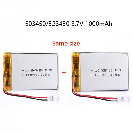
Below are the parts that you will need to complete all 6 labs.
The labs were constructed around the following parts photos are included as the part name does not describe the full pinout and breakout board attached to the parts.
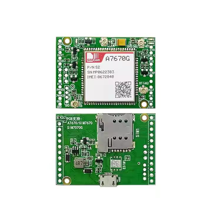
LTE Modem – SIMCOM A7670G-LABE with Breakout
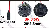
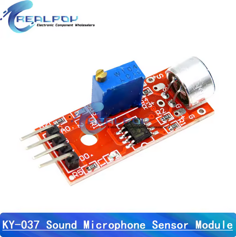
Requirements: Must Have SMS and Voice Capability and Must Have SPK+, SPK-, MIC+, MIC- pinout
Best places to look are AliExpress or Alibaba EBay and Amazon may have similar.
The G at the end is important aswell as it signifies Global Band compatibility.
I recommend one with the pins already soldered translation is a little poor so they may call it ‘With Welding’
Create a functional text-messaging interface and a utilities application of your choosing for your ESP32-based litePhone using EEZ Studio and the TFT_eSPI library.
Objective:
Enhance your litePhone project by implementing additional core functionalities, including a robust text-messaging interface and a practical utilities application. This lab provides an opportunity to showcase creativity and technical proficiency in designing user-focused applications.
Part 1 – Text Messaging Interface
Design a straightforward, user-friendly text-messaging interface using EEZ Studio and TFT_eSPI to interact seamlessly with the GSM module.
Requirements:
Your messaging interface must:
Allow users to compose, send, and receive SMS messages
Display conversations clearly with timestamps and sender identification
Include navigation between different conversations
Provide clear notifications for incoming messages
🏆 Challenge
Implement message threading for clearer organization. Document your implementation decisions and any challenges encountered.
Part 2 – Custom Utilities Application
Choose and implement one additional utility application tailored to enhance the litePhone experience. Examples include:
Calculator
Alarm/Clock
Battery Monitor
Simple Calendar/Reminder App
Requirements:
Your utilities application must:
Serve a clearly defined and practical purpose
Be intuitive and easy to navigate
Use consistent UI elements with previous litePhone applications
🏆 Challenge
Integrate battery monitoring and alert functionality within your chosen utility, providing real-time feedback on battery status.
Part 3 – Integration and Testing
Steps:
Thoroughly test your text messaging and utility application for usability and reliability
Conduct end-to-end testing, ensuring both functionalities integrate smoothly with the existing litePhone applications
Optimize and refine based on testing outcomes
Submit the following:
EEZ Studio project files
Source code for text messaging and utilities application
Photos or video demonstrating:
Sending and receiving text messages
Your custom utility app functionality
Short report (1–2 pages) including:
Overview of your application designs
Justification for your chosen utility application
Iterations, revisions, and outcomes
Lessons learned
Grading (100 Points)
Text messaging functionality and clarity (20 Points)
Custom utility application practicality and usability (20 Points)
Integration quality with existing litePhone system (20 Points)
UI responsiveness and intuitive design (20 Points)
Lab Report comprehensiveness and insights (20 Points)
Learn how to create a streamlined, low distraction User Interface (UI) using the TFT_eSPI library and EEZ Studio, designed specifically for making phone calls with your ESP32-based litePhone.
Objective:
Gain practical experience designing an intuitive, minimalist UI tailored for communication tasks on embedded hardware. This lab emphasizes simplicity and usability, crucial for developing efficient and focused embedded system applications.
Part 1 – UI Design in EEZ Studio
Use EEZ Studio and the TFT_eSPI library to design and implement a low-distraction UI for initiating and managing phone calls.
Requirements:
Your UI must:
Display a clear, simple numeric keypad for dialing
Show incoming call notifications clearly
Include intuitive controls for call acceptance, rejection, and termination
Minimize on-screen distractions and animations to ensure clarity and focus
Match the resolution and capabilities of your TFT display
🏆 Challenge
Explore principles of minimalist UI design. Implement techniques such as reduced color palettes or simplified button layouts to enhance usability. Document your design choices clearly.
Part 2 – TFT_eSPI Integration and Coding
Steps:
Implement functionality:
Dialing interface
Call handling logic (accept, reject, hang up)
GSM module (e.g., A7670G) integration for making and receiving calls
Optimize the UI refresh and interaction speed to ensure responsive behavior
🏆 Challenge
Test and optimize touch sensitivity and response times. Aim for seamless interaction to ensure intuitive call management. Document any specific optimizations or issues encountered.
Part 3 – Integration and Testing
After implementing your UI:
Test UI functionality extensively with live GSM calls
Evaluate responsiveness, intuitiveness, and overall user experience
Identify usability issues and iterate the UI accordingly
Submit the following:
EEZ Studio project files
Source code implementing TFT_eSPI UI
Photos or short video demonstrating:
Dialing a call
Receiving and managing incoming calls
Overall UI functionality
Short report (1–2 pages) including:
Overview of your UI design approach
Specific choices made to minimize distractions
Iterations, revisions, and rationale for changes
Lessons learned
Grading (100 Points)
UI design clarity and minimalism (20 Points)
Functionality and GSM integration (20 Points)
Responsiveness and usability (20 Points)
Overall integration with hardware components (20 Points)
Learn how to utilize Electronic Design Automation (EDA) software like EasyEDA to design your custom PCB and use JLCPCB’s SMT (Surface-Mount Technology) manufacturing service to fabricate your board.
Objective:
Gain hands-on experience with EDA tools by designing, validating, and preparing a PCB specifically tailored for your litePhone project. Additionally, familiarize yourself with the industrial manufacturing process by submitting your design to JLCPCB for professional fabrication and assembly.
Part 1 – PCB Design using EasyEDA
Use EasyEDA, a user-friendly, browser-based EDA tool to create your custom PCB design tailored for your ESP32-based litePhone.
Requirements:
Your PCB must include:
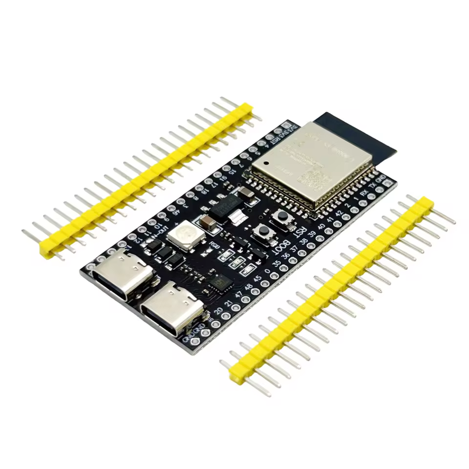
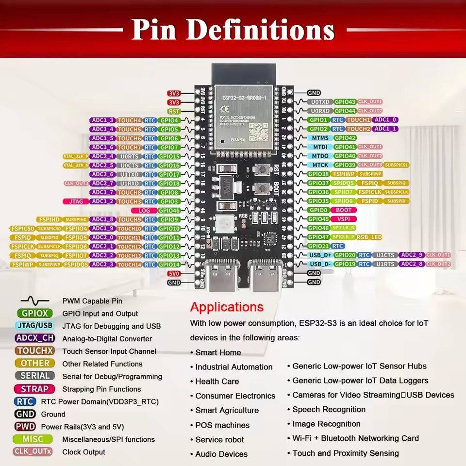
ESP32 footprint for the selected ESP32S3 MCU
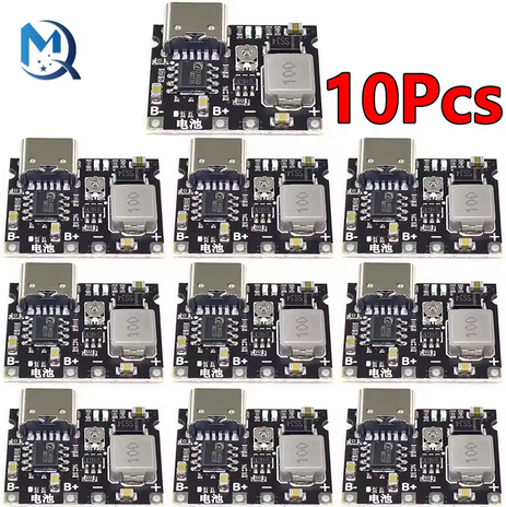
Footprints for necessary components: GSM module (e.g., SIMCom A7670G), battery management circuit, SIM card slot, audio components (speaker, microphone), TFT connector, and USB interface
Proper schematic capture clearly showing connections between components
PCB layout following best practices:
Adequate spacing for SMT assembly
Clear silkscreen labels
Appropriate power and ground plane utilization
Mounting holes and connectors clearly defined
🏆 Challenge
Optimize your PCB layout to minimize signal interference and improve power efficiency. Document the considerations taken.
Part 2 – Preparing Gerber Files and BOM for JLCPCB
Export the following files necessary for manufacturing:
Gerber files (used by JLCPCB to manufacture your PCB)
Bill of Materials (BOM) file, formatted for JLCPCB’s SMT assembly service
Component Placement File (Pick and Place)
Steps:
Verify design rules using EasyEDA’s Design Rule Check (DRC)
Export Gerber files, BOM, and Pick and Place files directly from EasyEDA
Cross-verify each file for accuracy and completeness
🏆 Challenge
Review JLCPCB’s SMT library beforehand. Select components readily available in their library to ensure smooth assembly.
Go step by step instead of showing a video and making them follow the steps add checkpoints for each student to check up on Specify slicer. Change lab report to a single page; add any problems you encountered.
Learn how to use simple Computer Aided Design (CAD) and Computer Aided Manufacturing (CAM) software to design and FDM print a simple enclosure for your litePhone.
Objective:
Gain hands-on experience with Computer-Aided Design (CAD) and Computer-Aided Manufacturing (CAM) by designing, slicing, and 3D printing a functional enclosure for your litePhone project. This lab bridges the gap between software/hardware integration and physical product design—a crucial aspect of embedded systems development.
Part 1 – CAD Modeling
You will use a beginner-friendly CAD tool like Tinkercad, Fusion 360, or FreeCAD to design a case for your ESP32-based litePhone. Your design must consider the size and layout of your hardware.
Requirements:
Dimensions must match your TFT screen, ESP32 DevKit, and any other mounted modules (buttons, battery, SIM card slot, speaker, etc.).
The enclosure must:
Be a two-part shell (top and bottom)
Include slots to secure components
Have cutouts for the screen, USB port, power/reset buttons, and ventilation if needed
Be printable on an FDM printer
🏆 Challenge
Research how to design snap-fit mechanisms or friction-fit lids. Try to implement one in your design!
Part 2 – CAM Workflow
Use a slicer like PrusaSlicer, Ultimaker Cura, or Bambu Studio to prepare your STL for FDM printing.
Steps:
Export your model from the CAD tool as an .STL file
Import into your slicer of choice
Preview and export the G-code
Print using the lab’s 3D printer or submit the file for instructor printing
🏆 Challenge
If supports are needed for overhangs, try modifying your model to eliminate them instead. Document your reasoning.
Part 3 – Assembly and Testing
Once printed:
Test the fit of each component
Identify any tolerance issues
If the screen or USB doesn’t align, revise and reprint
You should aim for snug but non-damaging fits
Submit the following:
CAD File (.f3d, .step, or equivalent)
G-code/Slicer File
Photos of:
Assembled Enclosure
Internal View (open shell with components)
Short report (1–2 pages) including:
Overview of your design
Design decisions (cutouts, fastening, part placement)
Any iterations and what changed
Lessons learned
Grading (100 Points)
CAD Design matches hardware (accurate dimensions, cutouts) (20 Points)
Printability and slicer setup (20 Points)
Physical print quality and usability (20 Points)
Functional fit of components (20 Points)
Lab Report comprehensiveness and insights(20 Points)
The TFT_eSPI library is a widely adopted tool in the embedded systems world, especially among developers working with 32-bit microcontrollers like the ESP32. This lab will introduce you to core concepts in UI rendering, event-driven design, and SPI-based hardware control. You will also use EEZ Studio, a modern UI prototyping environment, and LVGL (Light and Versatile Graphics Library) to design interactive components.
All materials from previous lab are required!
Part 1 – Wiring
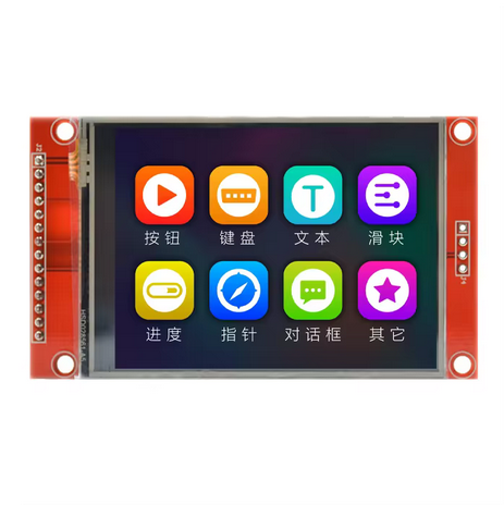
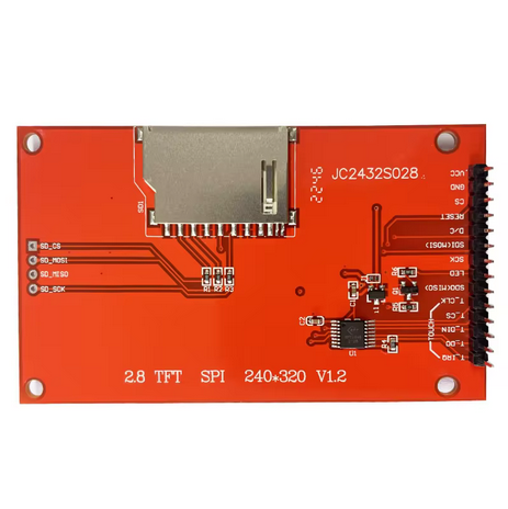
Begin by physically wiring your ESP32 to the TFT+Touch combo module. Here’s the suggested pinout for a ILI9341 and XPT2046 combination:
Display
Description
ESP32 Pin
TFT_IRQ
Interrupt Pin
3
TFT_CS
Chip Select (TFT)
7
TFT_MOSI
Master Out (also TOUCH_DO)
6
TFT_MISO
Master In (also TOUCH_DIN)
5
TFT_SCLK
SPI Clock
4
TFT_DC
Data/Command Select
8
TFT_RST
Display Reset
10
TFT_LED
Backlight Power
3.3V
TOUCH_CS
Touch Chip Select
15
TOUCH_IRQ
Touch Interrupt
3
🏆 Challenge
Explain why MISO/MOSI/SCLK are shared between the display and touch controller. Include a short paragraph in your lab report about SPI multiplexing and its implications.
You should now have a blank white screen powered and ready.
Open Arduino IDE, and go to File > Preferences, then set the Sketchbook Location to the root of the unzipped folder (where /ui/ and /libraries/ are located).
Change Build includes settings from lvgl/lvgl.h to lvgl.h
These Tutorials May Help:
Part 3 – Build & Flash
Compile the EEZ project and generate the output files.
Overwrite the ui.ino in /ui/ with the new one generated by EEZ Studio.
Open ui.ino in Arduino IDE and upload it to your ESP32.
You should now see your home screen on the display.
With this make a home screen with a button that leads to a “Hello, World!” page.
Part 4 – Touchscreen
In your ui.ino, add the following code to enable touch input. This is not plug-and-play—read it carefully and understand each function; you will figure out where to place this code.
Introduction lab; the transitional lab from Computer Hardware to Computer Architecture. Introduces the use of GSM AT commands and a refresher on communication with Espressif Systems and Arduino style 32-bit MCU.
Material(s) Required
IlI9488 Display or Similar see here (Scroll to Display list)
On the top toolbar: Go to Tools > Board > Boards Manager
Or use the keycombo Ctrl + Shift + B
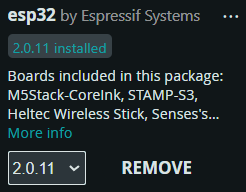
4. Search ‘Esp32’
5. Install version 2.0.11 of ‘esp32’ by Espressif Systems
6. Plug your ESP32 into your computer
7. Once plugged in select your board from the Upper Toolbar if it is not selected for you already
Part 2 – Modem Setup
Modem
Description
ESP32 Pin
5-12V
Power (5V 2A from PSU)
5VIN
GND
Common Ground
GND
RX
UART RX Pin
16
TX
UART TX Pin
17
Wire your Modem to the ESP32
In instances where the Modem requires above 3.3V you may need and external 5V power source.
Desktop Power Supply or a Breadboard with a AC to DC shield in 5V mode.
With your SIM inserted into your modem upload the following code to it.
#include <HardwareSerial.h>

// Define the UART connection between ESP32 and A7670G
HardwareSerial simModule(1);  // Use UART1 of ESP32

const int rxPin = 16;  // Set this pin for receiving data from A7670G
const int txPin = 17;  // Set this pin for transmitting data to A7670G
const long baudRate = 115200;  // Default baud rate for A7670G

void setup() {
  // Initialize Serial Monitor
  Serial.begin(115200);
  while (!Serial) {
    ;  // Wait for Serial Monitor to connect
  }

  // Initialize UART for A7670G
  simModule.begin(baudRate, SERIAL_8N1, rxPin, txPin);
  Serial.println("ESP32 and A7670G setup complete. Type AT commands in the Serial Monitor.");

  // Check if A7670G responds to AT commands
  sendATCommand("AT");  // Basic test command
}

void loop() {
  // Send commands to the module from Serial Monitor
  if (Serial.available()) {
    String command = Serial.readStringUntil('\n');
    sendATCommand(command.c_str());
  }

  // Print the module's response to the Serial Monitor
  if (simModule.available()) {
    Serial.write(simModule.read());
  }
}

// Function to send AT command to the A7670G module
void sendATCommand(const char* command) {
  simModule.println(command);  // Send AT command to A7670G
  delay(500);  // Wait for the module to process
}
4. Once the code has successfully compiled and flashed; open the Serial Monitor and send ‘AT‘. If you get a readable, non-gibberish you should be ready to go!
5. Send your modem AT+CSQ=? command to check its signal strength if the first number is in the 2-98 range you should be ready for the next steps!
6. Read the AT Command guide to figure out how to do more with the modem!